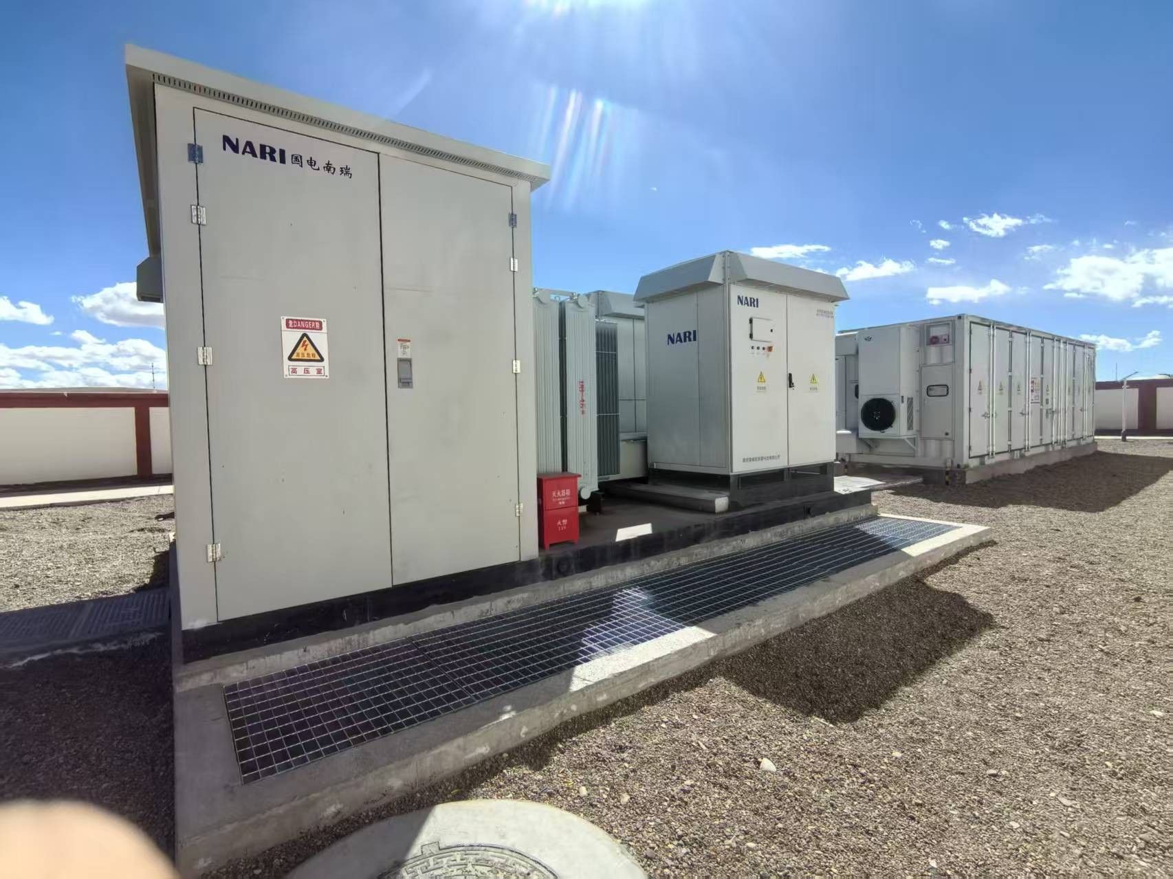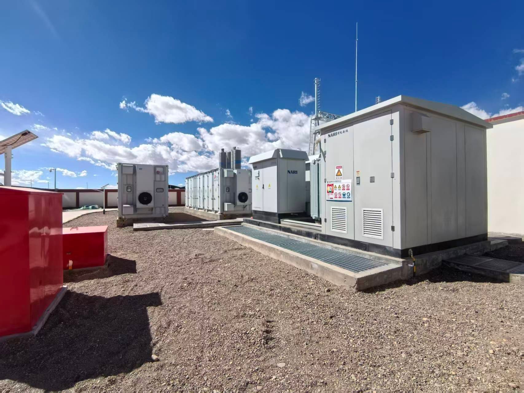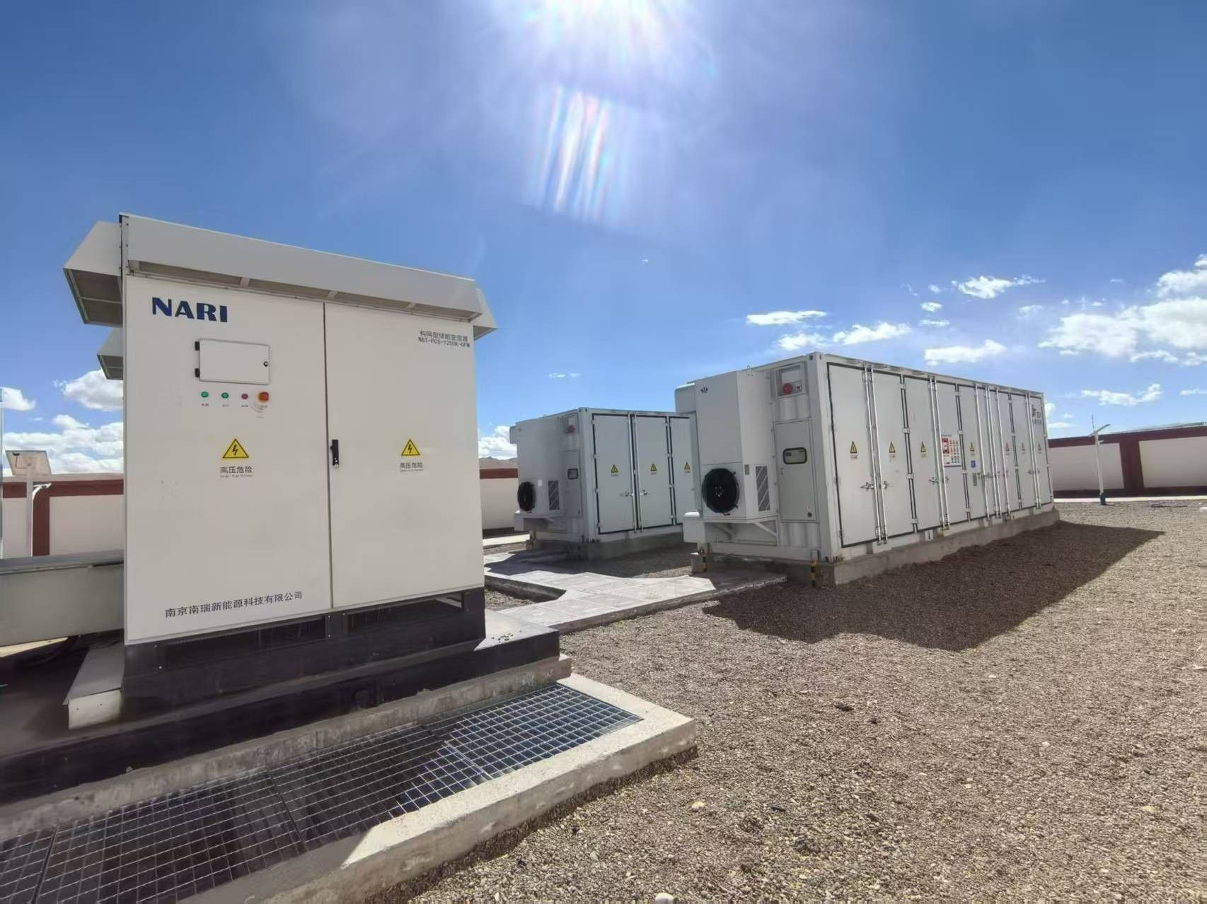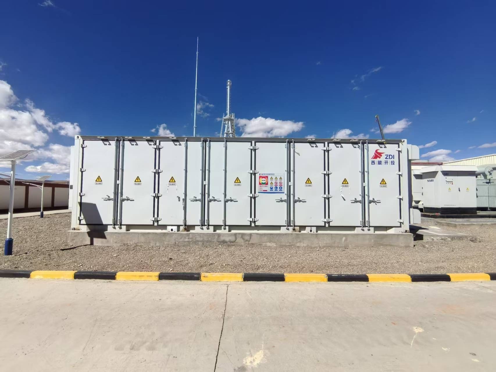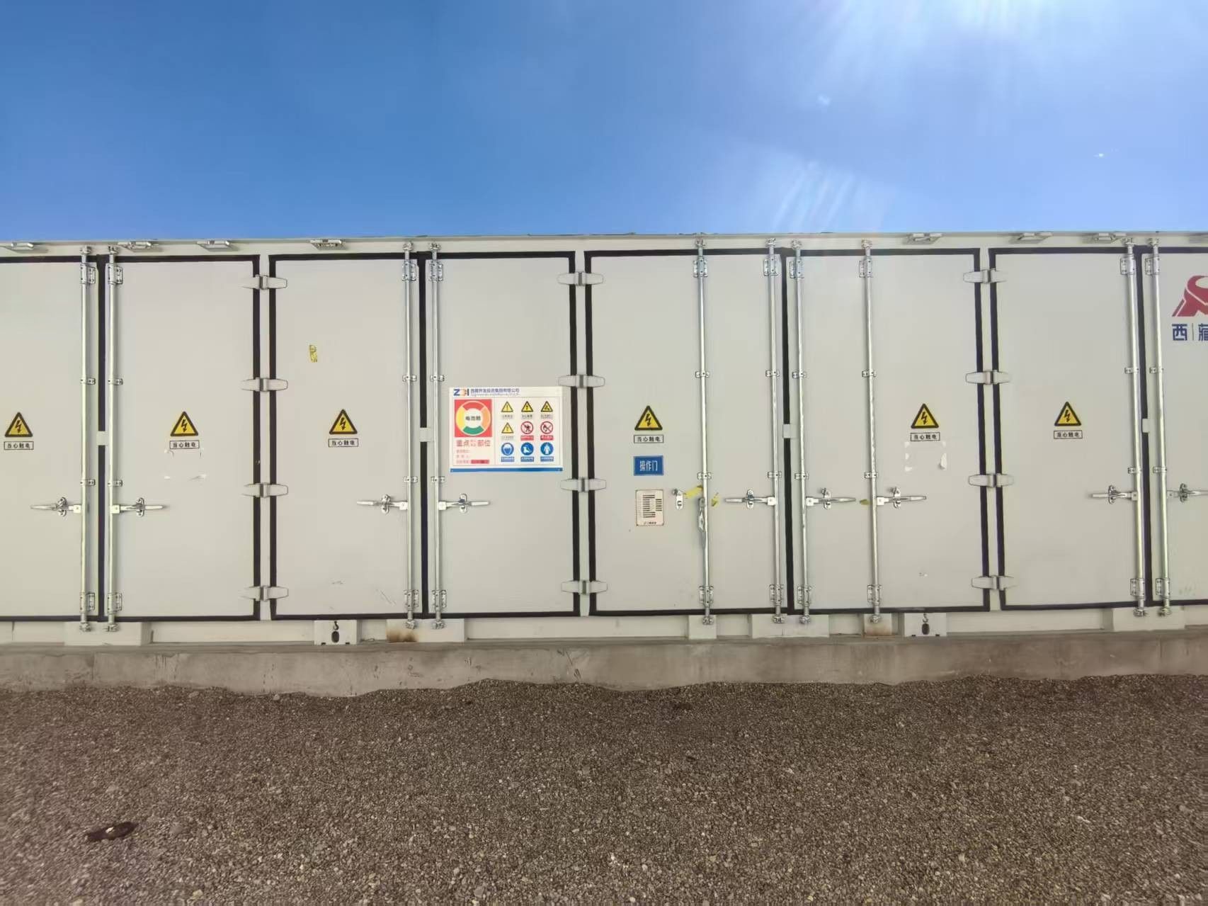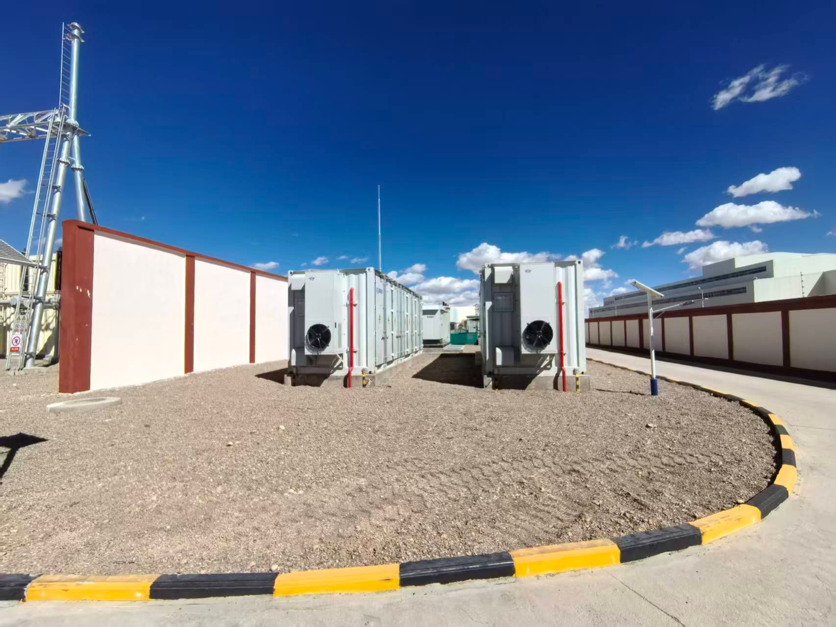

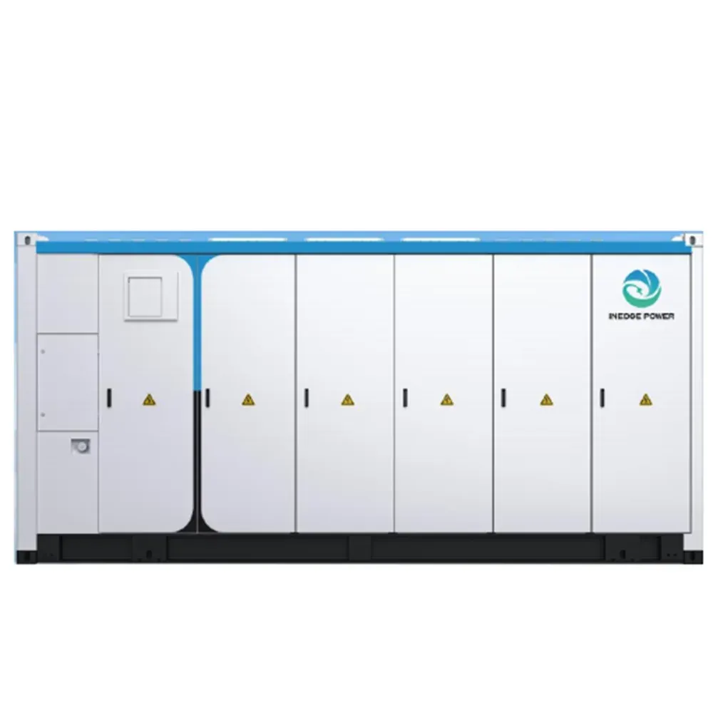
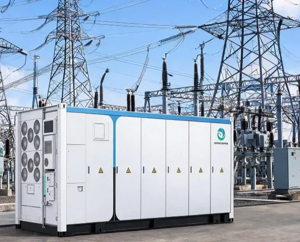
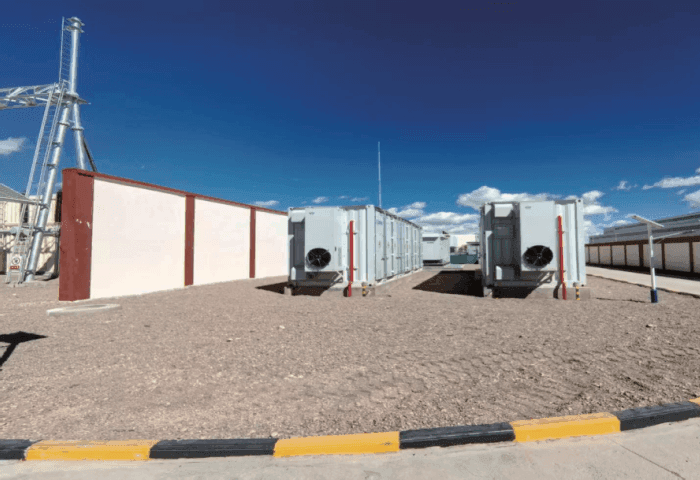
Tibet Kunlun 2.5MW/10MWh Grid-Forming Storage: Active Voltage and Frequency Construction at a High-Altitude Weak-Grid Node
Tibet’s grid-forming storage landscape has moved into hundred-megawatt-scale validation. Against that backdrop, a 2.5MW/10MWh system is not a scaled-down version of a bulk plant. It is a precision deployment for a terminal node, a single feeder, or a local microgrid—a configuration whose value lies not in capacity, but in whether it can shift storage from following the grid to constructing voltage and frequency references under the combined pressures of very low short-circuit ratio (SCR), high-altitude physics, and multi-unit coordination. The Kunlun project’s relevance is as a replicable engineering sample for that node-level role.
Why a Terminal Node Needs Grid-Forming, Not Grid-Following
Tibet’s terminal grid structure is defined by long radial connections, single-circuit supply, and low local short-circuit capacity. In parts of Ngari, the grid reaches the main system through a single 110kV line approximately 500km away; renewable penetration is high relative to local grid strength, and PV output has historically been capped by export limits. Under such conditions, grid-following inverters depend on a phase-locked loop to track grid voltage. As SCR falls below the critical range, synchronizing stability degrades sharply, and recovery after a disturbance is not guaranteed.
Grid-forming storage operates on a different premise: it establishes its own voltage and frequency reference, delivers short-circuit current support during faults, and behaves as a voltage source in steady state. Quantified research shows that GFM integration can raise the system’s critical SCR from 1.07 to 1.52, shifting the wind penetration limit upward accordingly. For Tibet’s many “resource-rich, strength-poor” terminal nodes, that SCR margin is the core value proposition.
Three Compounding Constraints: Altitude, Grid Strength, and Multi-Unit Coordination
The difficulty is not any single function, but the overlay of three physical and control constraints.
Altitude compresses the device’s physical envelope. Above 4,500m, reduced air density degrades air-cooling effectiveness and lowers the dielectric strength of insulating media. Industry assessments indicate passive cooling efficiency can drop by 20–30% at altitude, while partial-discharge risk rises as effective electrical clearances shrink. The response is not simple derating: IGBT module thermal paths, reactor insulation structures, and cabinet-level clearances require targeted redesign.
Weak-grid conditions tighten control bandwidth requirements. At low SCR, high grid impedance makes voltage far more sensitive to reactive injection, and frequency more responsive to active-power disturbances. The GFM control strategy must remain synchronously stable under very low SCR conditions. NR Electric’s PCS for the Amdo off-grid project was explicitly designed for “safe and stable operation under extremely low SCR,” combining voltage-frequency full feedforward with voltage-relaxation variable-structure multi-unit parallel control.
Multi-unit coordination amplifies consistency risk. A 2.5MW/10MWh system is typically built from multiple parallel PCS units. In a weak grid, circulating-current suppression and output consistency become harder: small parameter deviations between units can evolve into sustained oscillation or unequal power sharing. Goldwind’s plant-level short-circuit test at Naqu (20MW/80MWh, >4,500m) provides a measured benchmark: 3× rated current support during an artificial fault, transient response time deviation below 1%, and amplitude deviation below 5% across parallel units.
What a 2.5MW/10MWh Configuration Must Get Right
At this scale, the design objective is stability rather than scale. Three adaptation points emerge from disclosed Tibet engineering practice.
Control parameters must be derived from the point-of-connection SCR, not copied from templates. A standard VSG tuned for a strong grid can exhibit transient power oscillation when SCR is below 1.5. Sineng’s Naqu installation uses virtual synchronous generator control with a cluster-level AC/DC integrated architecture, enabling coordinated response across dozens of PCS units and maintaining an autonomous voltage-frequency reference when islanded. For a 2.5MW system, inertia and damping constants need site-specific relaxation based on measured grid impedance.
Overload capability is a hard threshold, not a margin. Weak-grid faults produce deep voltage sags and slow recovery. A GFM PCS without sufficient short-time overcurrent capability cannot establish voltage support at the fault instant. 3× rated current support appears as a validation metric across multiple Tibet projects and should be treated as a baseline requirement for 2.5MW/10MWh weak-grid deployments.
Black-start and islanded operation determine the upper bound of the use case. The value of a terminal node is not limited to grid-connected support; it extends to post-fault self-restoration. Tibet’s first GFM black-start field test, conducted at Coqên County, validated the full sequence of independent voltage-frequency reconstruction and load restoration without external grid support. For a 2.5MW/10MWh system positioned as a terminal resilience asset, black-start capability belongs in the base functional set.
Why This Node-Level Sample Matters
A 2.5MW/10MWh project will not dominate headlines. But the capability set it validates—high-altitude environmental adaptation, low-SCR stable operation, multi-unit synchronized support, and islanded grid formation—maps directly onto the requirements of Tibet’s terminal county grids, mining microgrids, and border-area supply nodes. Hundred-megawatt projects prove that GFM storage can scale. Node-level projects answer a different question: whether GFM storage can serve as a replicable voltage-frequency anchor at the weakest points of the grid, with an engineering configuration that supports economic deployment at volume. For the commercial case of grid-forming storage, that answer matters as much as the headline projects.
FAQ
What applications suit a 2.5MW/10MWh GFM system?
Terminal feeder nodes, single-substation voltage/frequency support, county or mining microgrids, and resilience nodes requiring black-start capability—rather than centralized storage for GW-scale renewable bases.
What is the dominant high-altitude constraint?
Reduced cooling effectiveness and compressed insulation margin. These limit fault-current duration and long-term reliability, and must be addressed through thermal-path and insulation redesign rather than power derating alone.
Grid-forming vs. grid-following in a weak grid—what changes?
A GFL inverter relies on the grid for its voltage-frequency reference and loses synchronizing stability as SCR falls. A GFM inverter generates its own reference and maintains local voltage-frequency stability in weak-grid and islanded conditions.